|
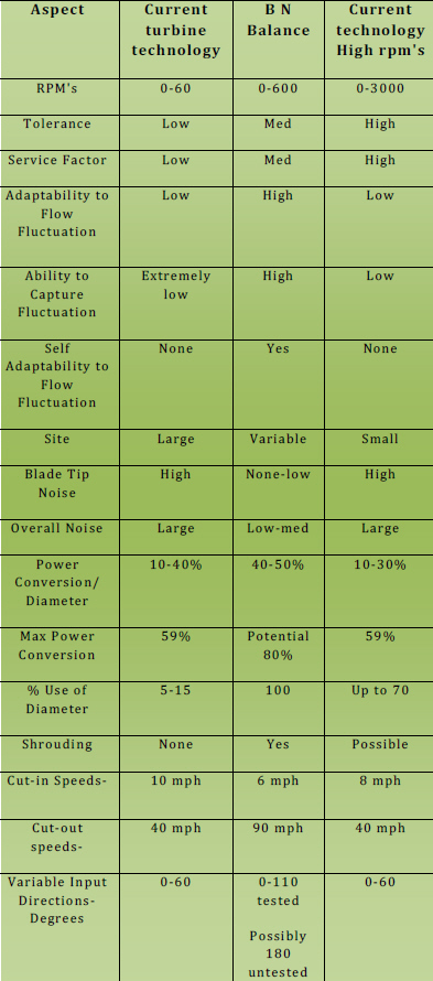
 How does the BNBES wind and water turbine differ from other turbines?
Standard Turbines:
Long thin aerodynamic wings fly through the air and develop their power by leverage.
Standard turbine surface area, in a given diameter, that is in contact with the fluid for energy transfer is only 5-15% of the total swept area.
Swept Area:
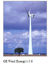
The area through which the rotor blades of a wind-turbine spin, as seen when directly facing the center of the rotor-blades. The power output of a wind turbine is directly related to the swept area of its blades.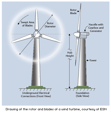 The larger the diameter of its blades, the more power it is capable of extracting from the wind. The larger the blades, the stronger they need to be to withstand the higher levels of centrifugal and cyclic varying gravitational loads. With a 31m (100 ft) blade weighing around 4.5 tons and a 54m (177 ft) blade weighing around 13 tons the weight of the blade is not proportional to the size and power rating of the machine. Each extra meter of length requires extra strength and adds further to the structures weight and so compounds the problem. Furthermore, the bending moments across the swept area of the blade can vary considerably with a possible difference of several meters a second in wind speeds between the top and the bottom of the blades rotation. This all adds up to a substantial increase in fatigue, not only in the blade structure but the machines hub, bearing, drive shaft and support tower. The larger the diameter of its blades, the more power it is capable of extracting from the wind. The larger the blades, the stronger they need to be to withstand the higher levels of centrifugal and cyclic varying gravitational loads. With a 31m (100 ft) blade weighing around 4.5 tons and a 54m (177 ft) blade weighing around 13 tons the weight of the blade is not proportional to the size and power rating of the machine. Each extra meter of length requires extra strength and adds further to the structures weight and so compounds the problem. Furthermore, the bending moments across the swept area of the blade can vary considerably with a possible difference of several meters a second in wind speeds between the top and the bottom of the blades rotation. This all adds up to a substantial increase in fatigue, not only in the blade structure but the machines hub, bearing, drive shaft and support tower.
Source: European Commission
Encyclopedia of Science
Transport Concepts & Designs (partner site)
The turbines that use this propeller style are subject to the Betz Limit and in order for this style to produce their 40% efficiency their tip rotation has to be as much as 7 times faster than the incoming fluid flow, therefore this accounts for the noise problem.
(Solar Today Magazine, Seth Masia, Big Power from Small Wind, Fall 2008)
Basic turbine information:
The capture (transfer) of energy to the turbine can only happen from contact with a kinetic rich energy source. What this means, is any turbine blade that has not contacted the kinetic fluid cannot extract any power from that moving fluid. The conservation of energy law states that energy can only be transferred and is never made. In this transfer there is always loses with the amount of loss dependent on the forces of friction, turbine efficiency and the amount of contact each turbine has with the kinetic energy source.
A balance between lift and drag is highly strategic for the standard turbine wing. The primary reason for this is that these blades are long and skinny for this particular type of optimum performance. Billions of dollars of research has enabled these types of turbines to reach the goal of 40% efficiency. This style of turbine is restricted by the Betz Limit, and also has no ability to accumulate any fluid from the laminar flow of the kinetic fluid stream. Therefore this style of turbine can easily miss the energy rich gusts or surges.
There are three basic ways to produce torque. This is the basis for all mechanical devices. Archimedes said if he had a lever he could move the world, so the first way is to have a long lever with weight substantial enough to prevent breakage of that lever. Several basic applications come to mind such as a car jack, pry bar and a shovel. The second aspect to the leverage is weight. An object in motion tends to stay in motion. This is why the old farm and construction equipment, steam locomotives and ships had large flywheels in order to keep the flywheel in motion. The high mass (weight) and slow speed (slow rpm) produces high torque for work needed. This was a popular method until the Second World War. One can still observe this method being used in the large wind turbines.
The advantage to this method is that it will ride through the fluctuation of variable inflows and somewhat continue to run after the fluid force has decreased with the hope of another infusion of energy. The negative effects are the over coming of inertia (start up). This is remedied by highly sophisticated pitching devices that mechanically rotate the blade into the fluid decreasing the starting drag. The cost and placements of this type of turbine avails itself well outside of high use areas (villages, towns, cities), making transmission cost and losses higher. There are some persons who think these turbines are aesthetically unappealing to the landscape. Noise can be problematic, because for the turbine to reach the 40% efficiency level, the tip of the rotor has to move as much as seven times faster than the static fluid speed, therefore some wind turbine tip speeds can equal the speed of sound.
The next most popular method of generating torque came with the advent of the two-stroke engine that produced high rpm and had little mass.
Engineers found that the higher rpm would compensate for less mass, providing the rpms were kept at sufficiently high, specified level. These advancements lead to a number of hand held devices such as chainsaws, weed whackers, leaf blowers, motorcycles, motorboats and to autos using the higher rpm low flywheel weight method. Some of the differences in rpms have been drastic. For instance, in cars in the 50's the basic rpms were less than 1000, and some cars today are upward into the 15,000-rpm range.
The advantages to this method for power production are that standard generators use rpms up to 3600rpm generators. The turbines can be light in weight and they can be produced cheaply. This method lends itself to the small turbine market for boats, RV's, cabins and homes. The disadvantages are that, wild fluctuations in startup (cut in speed), high pole resistance and low production at low fluid speeds can occur.
This smaller size turbine can also be equipped with a shroud. A shroud is an enclosure that funnels the fluid to the turbine and prevents the confined fluid from being centrifugally lost because it is recirculated within the turbine. This negates the Betz limit of maximum efficiency 59%, which all propeller type turbines are relegated to. By shrouding a turbine, the efficiency can be as high as 400% from that diameter. An illustration of this would be the jet airplane engines focusing large amounts of fluid into a small space for combustion providing the thrust for flight.
The third method is a combination of both prior methods with a bit of a twist. People all over the world for centuries have used the massive weight of the wind in conjunction with a light material (sail) to confine that massive weight and put it to use for them, moving almost everything conceivable. This is a system more over than a method. Using the weight of the fluid has benefits over the prior methods, which are light structure, moderate rpm, high torque and high resistance.
Torque is the ability to do work so utilizing more of what is transient, the moving fluid in this case acts as the agent to produce the power; using the fluid against itself to produce the power. To illustrate this system a parachute/spinnaker sail catches the air but needs to have a release of the confined fluid. If the fluid is released too fast, the faster the fall or slower sailing speeds will occur. If the release is too slow, the fluid may unevenly release billowing out too much on one side, up-ending or collapsing the chute /sail. The example of a parachute/sail for a turbine would hold the fluid to long and prevent new kinetic rich fluid form coming into the turbine, therefore preventing the continued power generating process. There are a number of machines with this excess drag and are referred to as drag machines.
The Dutch used a heavy structure on their windmill sail with a high release, therefore missing some of the available energy and efficiency. By the added weight they are back to the first method of leverage.
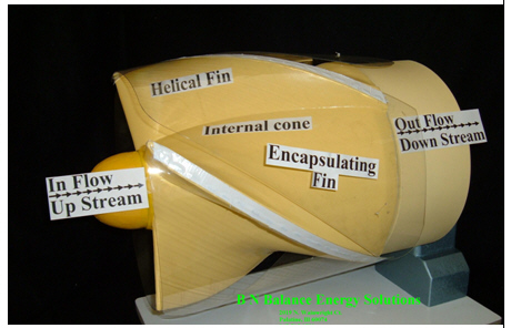
The BNBES turbine uses a combination of prior technologies.
Picture 1: B N Balance ES Wind Turbine
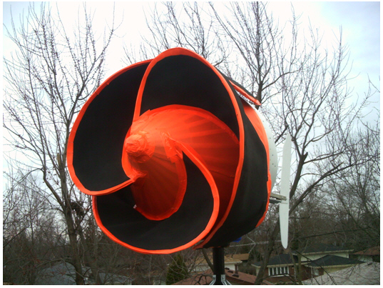
1. Part of the turbine accumulates and concentrates the energy.
2. Part of the turbine prevents the energy rich fluid from escaping (Shroud).
3. Part of the turbine flies helically through the fluid producing a rotation from the laminar (unified direction) moving fluid.
4. Part of the turbine focuses and speeds up the fluid to the ventures for exhaust. This allows for the higher amounts of kinetic rich fluids to come in contact with the turbine and preventing the accumulation of energy spent kinetic fluids
5. Soft materials for flexibility to prevent birds and fish injury
6. Slower speeds and high torque, lower tip speeds, therefore less noise
7. Wind version potentially continues generation up to 90 mph form 200 degrees inflow.
8. No motion smear, therefore completely visible to wildlife
Picture 3: Inflow view of the water version Turbine
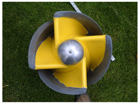
The BNBES Turbine utilizes the entire diameter of the swept area by means of the Bernoulli Equation, thus preventing loss of the accumulated energy that was sped up into an encapsulating fin/wing (self-shroud negating the Betz Limit). This is why the BNBES Turbine has captured a minimum 35% more than standard turbines.
The potential when fully optimized, of 300% more energy, will bring the abilities of open turbines past the Betz Limit, closer to levels of closed system turbines. The turbine can now capture wind gusts or faster surges of water that standard turbines will continue to miss. The turbine will absorb the surges with the flexible wing opening like a bird. The turbine can morph in to a larger turbine under high load demands automatically when needed.
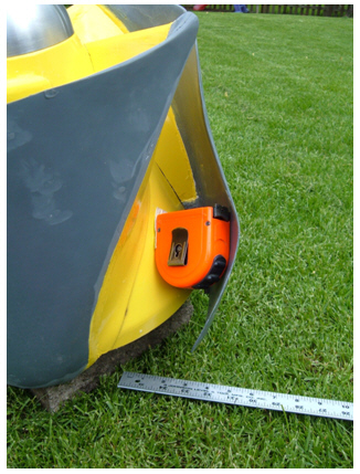
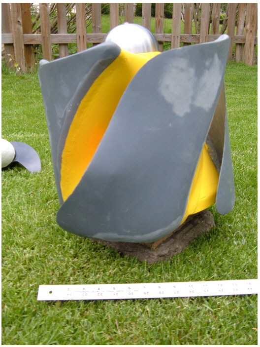
In Pic.4 you will see that the encapsulating fin (shroud) is flexible enough to allow a tape measure to be inserted in to the out flow portion of the turbine. This will allow wildlife the advantage to escape the turbine. The design, seen in pictures 1 and 4, shows the rotation always to the opening ejecting what ever is in the turbine to the outside.
Picture 4: Side view of turbine
In comparison with all the current thinking of turbine design, this turbine uses the most of technology available from the areas of new materials and proven scientific technologies of the past. The turbine answers the questions of the prior turbine technology, including power losses (Betz Limit), while incorporating the best of all the prior learned advances, leaving the less beneficial behind. The BNBES turbine goes one-step further into the future. The design itself continues to produce power in greater amounts and is the only known turbine, to the best our knowledge, that actively limits the damage to the inhabitants of the fluid man is seeking to use to harvest clean, renewable energy.
Picture 5: Side view of turbine
|
|


